My original SYM-1 system.
The following pictures show the first SYM I built. It was basically kept stock as no modifications were done to the firmware (well almost). This system used a tape recorder to store and retrieve the files. As floppy drives became available, I realized that I would not be able to install the floppy controller and more memory the way the system was built. Hence, the second SYM (actually, my wife always wanted to play either BASIC or The First Book of KIM games converted to work on the SYM). It was just easier to give her this one and build another one. This SYM contained a built in power supply with over voltage protection, 14K of user ROM (8K shared between BASIC or RAE depending on jumper selection) and a total of 9K of RAM. A 4K ROM located at $9000 contained several FBOK games and could be played with a J 1 to J 7 from the SYM ROM (I altered the jump table). The other 2K EPROM located at $F000 contained several BASIC enhancements including a renumber program, auto line number, the trig patch and an editor which needed a buffer area. I used location $A800-$ABFF for this. This was easy as the SYM already had this address space decoded and I never wired this SYM for the user supplied 6522 which used this address location.
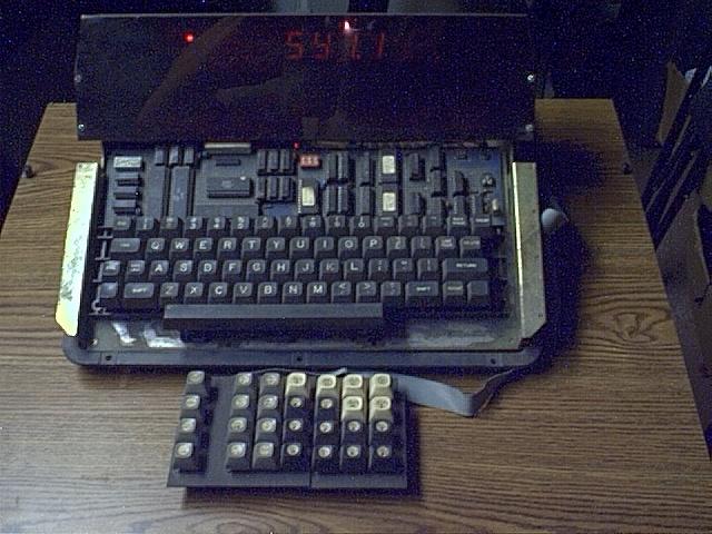
The first picture shows the homemade KTM2/80, SYM keyboard and jumbo display.
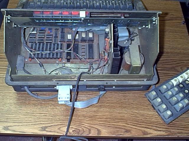
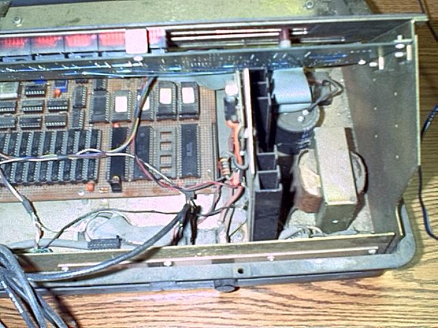
Picture from the back showing SYM and power supply. Note jumper located in front center of large chip (6502). This is used to select between RAE or BASIC, originally in all four sockets occupying $B000 - $EFFF, which are now piggy-backed shown in top right using $C000 - $DFFF. RAE was re-compiled from original $B000 - $BFFF & $E000 - $EFFF to the $C000 - $DFFF locations where it currently resides. The missing chip is U-29 (6522) which was not necessary for what the SYM was being currently used for. Connector in back went to hex keypad. Not shown is a DB25 connector located between the power cord and connector (bottom left). This connector was for the use of my printer as well as the connections for the tape recorder.
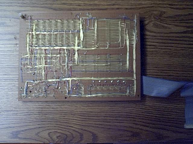
This is the main board. The cable on the lower left is soldered to headers that plug into the original sockets for the 7 segment on board display. I used this to run the jumbo display shown in the first picture. Actual board size is 8" X 6".
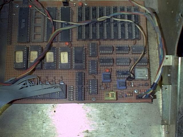
This is the bottom of the main board. All my projects used point to point wiring. I found wire wrapping to messy and took up a considerable amount of height space.
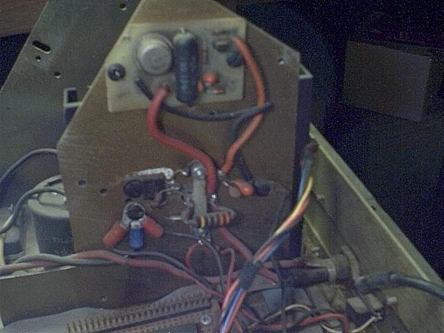
The power supply showing black heat sink for 5 volt regulator.
Over voltage and 5 volt regulator board.